ATM - Concepts and Architecture
Cell-Relay provides a compromise between fixed synchronous
allocation mechanisms and bursty, routable packet interfaces.
The Asynchronous Transfer Mode (ATM) protocols and architecture
have managed to gather an impressive amount of market and media
attention over the last several years. Intended as a technique to
achieve a working compromise between the rigidity of the telecommunication
synchronous architecture and packet network's unpredictable load behavior,
ATM products are appearing for everything from high-speed switching to
local area networking. ATM has caught the interest of both the
telecommunications community as a broadband carrier for Integrated Services
Digital Network (ISDN) networks as well as the computer industry,
who view ATM as a strong candidate for high-speed Local Area Networking.
This article covers the basic concepts involved in the ATM architecture.
At the core of the ATM architecture is a fixed length "cell."
An ATM cell is a short, fixed length block of data that contains a short
header with addressing information, followed by the upper layer traffic,
or "payload." The cell structure, shown in Figure 1, is 53 octets
long, with a 5 octet header, followed by 48 bytes of payload.
While the short packet may seem to be somewhat inefficient in its ratio of
overhead to actual data, it does have some distinct advantages over the
alternatives. By fixing the length of each cell, the timing characteristics
of the links and the corresponding network are regular and relatively easy
to predict; predicting the dynamics of variable length packet switched
networks isn't always easy. By using short cells, hardware based switching
can be accomplished. Finally, the use of short cells provides an ability
to transfer isochronous information with a short delay.
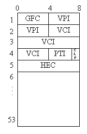
Figure 1 - ATM Cell Structure (UNI Format)
The information contained in the header of each cell is used to identify
the circuit (in the context) of the local link, carries local flow control
information, and includes error detection to prevent cells from being mis-routed.
The remaining 48 octets are routed through the network to the destination using
the circuit.
ATM has evolved over the last 5-10 years to include a wide range of support
protocols. Routing and congestion management, have been particular areas of
research. The early concepts of cell transfer networks revolved around the
thought that users could "reserve" a pre-specified amount of
traffic through a circuit on the network. Some amount of guaranteed throughput
would be provided with an additional amount only as needed. Then, through this
contract, traffic in excess of the pre-allocated bandwidth could be arbitrarily
dropped if congestion problems occurred. However, the complexities of
implementation have proven these techniques to be far too difficult.
Several vendors have proposed flow control architectures that involve more
active windowing protocols between the switches for data traffic.
ATM Architecture
As in the case of many large systems, there are a range of components
and connections involved in the ATM networks. Figure 2 shows an example
network architecture. All connections in the ATM network are point-to-point,
with traffic being switched through the network by the switching nodes.
Two types of networks are included in the ATM architecture, Public Networks
and Private Networks. Private Networks, often referred to as Customer Premises
Networks, are typically concerned with end-user connections, or bridging
services to other types of networks including circuit switched services,
frame relay, and voice subsystems. The interface between the components
in the Private Networks is referred to as the Private User Network Interface
(UNI). ATM also extends into the wider area Public Networks.
Interfaces between the Public and Private network switches conform to the
Public UNI. Interfaces between the switches within the Public network are
the Network Node Interface (NNI).
Specifications for both the Public and Private UNI can be found in the
ATM Forum's publication "ATM User-Network Interface (UNI) Specification."
The private networks often permit the use of lower speed short haul interconnects
that are useful in LAN environments, but not of great use in wider area public
networks. Three types of NNI have been developed, NNI-ISSI that connects switches
in the same Local Area Transport Area (LATA), the NNI-ICI, that connects ATM
networks of different carriers (InterCarrier), and finally, a Private NNI
that permits the connection of different switches in a private network.
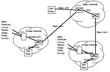
Figure 2 - ATM Sample Network Architecture
Protocol Reference Model
There is more to the ATM standards than the ATM cell format alone.
Specifications exist to describe acceptable physical signaling,
call control, and upper layer payload formats.
Figure 3 shows the hierarchy of protocols involved in ATM.
Mapping roughly to layers 1 and 2 of the OSI model, ATM is broken
into 3 distinct layers. At the bottom, several classes of
physical layers have been adapted to support the different types of
ATM applications. The ATM layer provides the cell-switching and
routing services. Application services rely on the ATM Adaptation
Layer (AAL) that serves two purposes, to provide a common framework
for the segmentation and reassembly of larger data sets into the ATM
cells and to provide service specific mechanisms for the transport
of different types of data. Four different classes of traffic are
supported by the AAL ranging from straight circuit switched data
through packet mode applications. Many of the early implementations
of ATM have been focused on the packet mode services, often as a backbone
for Frame Relay services. Typically, the AAL should be viewed as an
internal, software interface to bridge end-user services over ATM.
There is typically a good bit of work required to bind other protocols to
the ATM stack.
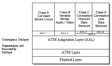
Figure 3 - ATM Protocol Architecture
Traffic Flow Through The Network
A two tiered addressing scheme is used with the following
elements being involved in the addressing assignments:
- Virtual Channel: A virtual channel represents the flow of a
single network connection data flow between 2 ATM end users.
The ATM standards define this as a unidirectional
connection between 2 end-points on the network
- Virtual Path: A virtual path is used to carry one or more
virtual channels through the network. It is represented
as a bundle of channels between the two end-points.
This logical grouping of paths and channels provides some flexibility
in managing the addressing of the flow of information through an ATM network.
Figure 4 shows a sample configuration of a network with an assortment of
Virtual Paths and Virtual Channels. As can be seen in the figure, each
virtual path contains one or more virtual channels. It is important
to note that the actual numbers assigned to each of the paths and
channels are used only to represent a Virtual Path or Channel segment
that exists between two adjacent nodes of the network. These values are
established when the actual Virtual Channel Connections (VCC) are established.
The number of Paths and Channels over a single link are limited by the ATM
cell format. This limitation helps to explain why there are differences
between the UNI and NNI formats. The NNI format replaces the 4 bits of the
Generic Flow Control indication with additional VPI bits, extending the
number of possible paths over the NNI from 256 to 4096.
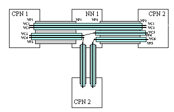
Figure 4 - Example ATM Circuit and Path Connections
Figure 5 shows the formats for the UNI and NNI cells. The fields in the ATM Cells are:
- GFC - (Generic Flow Control) used only in the UNI format.
No general purpose services have been assigned to this field,
and it is significant for only the local site. This flow
control information is not carried from end-to-end.
Two modes have been used for GFC based flow control,
"uncontrolled access" and "controlled
access." in uncontrolled access, this field is set to
all zeroes. In controlled access mode, this field is set when
congestion has occurred. The receiving equipment will report
instances in which the GFC has been set a significant number
of times to Layer Management.
- VPI/VCI - (Virtual Path Identifier/Virtual Channel Identifier).
The distribution of bits between these two fields can be
negotiated between the user and network equipment.
Referring back to Figure 4, these identifiers are used
to tag only the portion of the path/circuit connection over a
single link. It is the combination of all of the individual paths
and circuits that comprise the connection.
- PT - (Payload Type) Indicates whether or not the cell contains
use information or Layer Management Information. It also carries
implicit congestion information.
- CLP - (Cell Loss Priority). Indicates the cell's priority in the
ATM selective loss algorithm. Set by the initiating equipment,
when this set to 0, the cell is given preference over
cells with CLP set to 1.
- HEC - (Header Error Control). Provides a capability to correct
all single bit errors in the cell header as well as the
detection of the majority of multiple-bit errors. The use of this
field is up to interpretation of the equipment designers.
If most errors are likely to be single bit errors, it can
be used for error correction. Using the field for error correction does
carry some level of risk of introducing unwanted errant traffic
on the network should a mistake be made in the correction process.
Note that the circuit and path identification fields are used to indicate the path
that each cell is to take through the network. The identifiers carried in the cells
carry only the information required to identify the cell's route to the receiving
switch or end-point, they are not network addresses as is found in
the case of IP or OSI networks.
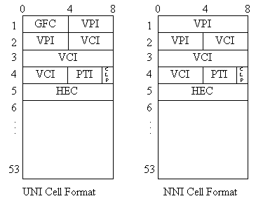
Figure 5 - ATM Cell Formats
This article covers some of the important general concepts in the ATM architecture,
but scratches just the surface. Other important areas of the ATM architecture
include how it is mapped to the various physical interfaces, the ATM Adaptation Layer,
signaling protocols, layer management, along with switching strategies.


