ATM Physical Layer Support
Multiple Carriers for the open cell-transfer standard.
One of the strengths of the Asynchronous Transfer Mode (ATM) standards
are the ability to configure networks that operate over a variety of
physical interfaces. With ATM applications ranging from use in Local
Area Networks (LANs) to providing backbone transit services for broadband
Integrated Services Digital Networks (ISDN) and Switched Multimegabit Data
Services (SMDS), the ATM User Network Interface (UNI) standard has specified
operation over 6 different physical interfaces. These include the Synchronous
Optical Network (SONET), DS3, 100 Mbps Multimode Fiber, 155 Mbps, E3, and E4.
There are several other interfaces that have been considered for use with ATM.
All of the ATM physical interfaces address a fundamental set of issues.
Speed, latency, and error rates are considerations. Given that ATM is most
frequently associated with high-speed networking, the bulk of the interfaces
deal with high speeds ranging from 25 Mbps to as high as 622.08 Mbps.
Latency, or propagation delays must be minimized to enable
ATM to provide services for a subset of its applications.
Interactive multimedia works best when transmission delays
are minimized. Finally, a fundamental requirement is that the
transfer error rates be minimized. As can be seen from the past
few columns, the ATM protocols are highly dependent on reliable
delivery. While several mechanisms are in place to detect errors and
prevent their propagation, the cell-transport mechanisms provide no
retransmission services. For reliable data services, the end-systems
typically are responsible for retransmitting frames.
This will result in a single bit error in a single cell causing the
retransmission of many cells to accommodate the AAL (or higher) retransmission.
The ATM physical interface standards also address Operations Administration
and Maintenance (OAM) services. Management services including performance
monitoring, fault management and performance testing are considered in
the Public interface specifications. The OAM functions are most typically
found in the public interfaces (e.g., SONET, DS-3) to address applications
in which long-distance connections must support remote management with a
high-quality of service.
In general, the ATM physical interface specifications are organized to
include two sublayers, the Transmission Convergence Sublayer, and the
Physical Media Dependent sublayer. The PMD provides the transceiver
services to physically transmit the ATM Cells and convergence information
between two adjacent ATM stations. The Transmission Convergence layer
can provide a range of functions beginning with basic Header Error
Check (HEC) generation and verification and Cell framing services.
Depending on the nature of the type of interface, additional channel
management services are often included. Strategies for framing the
ATM Cells include synchronous framing tied to the lower level channel
synchronization protocols (SONET, DS3, 155 Mbps) or based on asynchronous
line coding schemes (such as the use of FDDI framing in the 100 Mbps
fiber interface).
SONET / SDH
The ATM UNI specifies a 155.52 Mbps STS-3c frame for use when running ATM over SONET.
The SONET standards conveniently provide a payload format that can transport the
ATM cells along with OAM information. SONET includes a U-plane interface that is
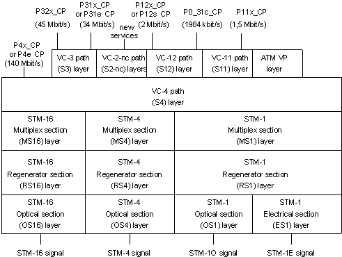
placed between the end user and network equipment. As shown in Figure 1, the
SONET U-interface is based on two primary layers, a Physical Media Dependent
(PMD) sublayer that provides the lowest level timing and physical interface support,
and a Transmission Convergence Sublayer, that provides the frame transfer and
verification services. Of these functions, the PMD and bottom half of the
Transmission Convergence Sublayer are derived from the Synchronous Digital Hierarchy
(SDH - the European version of SONET) and the upper half of the Transmission
Convergence Sublayer is specific to the Broadband ISDN specification.

Figure 1 - SDH Layer Functions
DS3
44.736 Mbps transmission services are provided by the DS3 Physical Layer interface.
The ATM specification is based on the T1E1.2/94-002R1 standard. As in the case of the
SONET interface, the DS3 physical interface is divided into a PMD and a Transmission
Convergence Sublayer. The DS3 information format is managed by a Physical Layer
Convergence Protocol (PLCP) that provides the mapping of the ATM cells onto the
existing DS3 carrier. The PLCP provides a set of services to map the ATM cells
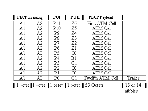
into the DS3 frame structure. With an 8-kHZ cycle time (125 us frame length),
each DS3 frame carries 12 ATM cells, with each cell framed by 4 octets of overhead
information. The overhead octets, shown in Figure 2, serve the following purposes:
- A1, A2 - provide frame alignment (A1 = 0xF6, A2 = 0x28)
- B1 - Bit interleaved parity - for path error monitoring
- C1 - Cycle/Stuff Counter - supports a three frame cycle in which additional
nibbles can be stuffed for alignment.
- G1 - PLCP path status - carries status feedback information to the distant
end of the participating link. Information transferred in this octet includes
a four-bit count of errors in the previous frame, a single-bit indicating that
a receive error has occurred. If not implemented the error counter is to be
set to 1111.
- Px - Path Overhead Identifier (POI) - provides an indication as to the use of
the following octet (can be Z1-Z6, B1, G1, or C1)
- Zx - Growth
- Trailer - filler to align cells within a regular 125 microsecond cycle time.
As a result of the framing overhead introducing each ATM cell within DS3,
the transport carries 40.704 Mbps.

Figure 2 - DS3 PLCP Frame (from ATM UNI Specification V3.1)
100 Mbps Multimode Fiber Interface
Based largely on work done for the FDDI PHY and PMD services, the ATM 100 Mbps
Multimode Fiber Interface is targeted towards the private UNI. Intended to support the
interconnection of computers, bridges, routers and the like, the local fiber interface
does not include the more extensive OAM functions found in SONET or DS3.
In place of the physical OAM services, the Interim Local Management Interface (ILMI)
specification defines a Simple Network Management Protocol (SNMP) Management
Information Base (MIB) for performing these functions.
While there are some functional differences between the private local interfaces
and public network ATM services, the 100 Mbps fiber specification is also broken into a
Transmission Convergence Sublayer and a Physical Media Dependent (PMD) Sublayer.
The PMD sublayer directly references the FDDI PMD specification (ISO DIS 9314-3).
The MIC connector and FDDI physical interface are specified. As in the case of the PMD
services, the ATM fiber interface makes use of the 4B/5B FDDI coding. With 4B/5B, each
5 bits transmitted on the line are used to represent 4 bits of encoded information.
A good bit of the additional code space (16 of the 32 codes represent data values)
is used to frame the cells for transmission. Several codes are left unused.
One of the more useful features of the 4B/5B encoding is that it enforces the
regular transmission of signals that force edge transitions. As a result, clock
recovery is enhanced, and decoding of the optical signals into electrical signals
is simplified. To achieve the 100 Mbps data transfer rate, the actual transceiver
bit rate is actually 125 Mbps. As opposed to the synchronous delivery of cells within
SONET and DS3, the fiber interface is completely asynchronous. Cells can start at any
time the line is idle.
155 Mbps Interface
The ATM 155 Mbps Interface is also based on a fiber-optic transport. Unlike the 100 Mbps
interface, the 155 Mbps interface is based on a synchronous delivery scheme (125 us
framing cycle). Specified in ITU-T recommendation I.432, the 155 Mbps also provides
overhead octets for transmission of OAM information similar to that described for the DS3
interface. 8B/10B encoding is used at a physical transmission rate of 194.4 MBaud.
The unencoded line frequency of 155.52 Mbps is identical to the SONET STS-3 rate.
The physical interface is 1300 nm multimode fiber using 62.5/125 micrometer diameter fiber.
While the specification indicates that operation is permitted with other types of fibers,
strong caution is provided that one should stick to the specified fiber. More detailed
specifications are provided for the connector and optical characteristics of the fiber
interface.
Shielded Twisted Pair
Intended to address the high-speed LAN market, the Shielded Twisted Pair PMD specification
is based on the same signaling that is used in the 155 Mbps fiber interface, only
operating over copper wire. Some of the general features of the STP interface include a
capability to span up to 100 meters, the ability to operate over existing 802.5 cable
plants, as well as matching the architectural requirements of EIA/TIA 568.
Electrical characteristics of the Shielded Twisted Pair interface require that cable
attenuation be no greater than 124 dB per kilometer when operating at 100 MHz.
Near end crosstalk should be limited to -38.5 dB. Information is transmitted over a
differentially driven interface with the output voltage differences ranging between
1 and 1.6 volts. A nine-pin connector is specified with 4 signal lines and a chassis
ground being used.
STP Transmission Convergence functions services include 8B/10B line coding (as in Fibre
Channel), physical layer framing with 27 cells being transmitted every 125 microseconds,
in-band physical frame synchronization, 125 microsecond clock recovery, HEC generation
and verification, and additional OAM services. Line coding is in accordance with the Fibre
Channel specification. The transmission frame structure has been organized to support
byte synchronization, frame synchronization, and the transmission of OAM information along
with the ATM cells. Once the overhead is accounted for, the resulting payload transmission
rate is 149.76 Mbps. The OAM information transmitted over the STP interface includes a
Far End Receive Failure (FERF) signal that is used to provide back-channel indication
that receive errors have occurred. An Errored Frame Indicator (EFI) is used to signal
that a frame has been received with a violation of the 8B/10B coding. Finally, an Alarm
Indication Signal is used to indicate that an upstream failure has been detected.
With its layered architecture, ATM has been designed to operate over a wide range of interfaces.


