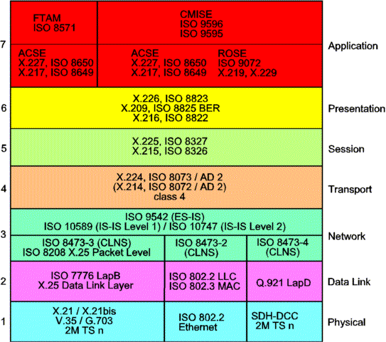
Figure 1 - OSI Management Stack
OSI Protocols
The Q3-Stack (OSI)
Q3 is a standardized management protocol which provides
routing facilities (Layer 3) within the network. Q3 is built by
the 7 Layer OSI stack with selected protocols forming a protocol
suite for TMN interfaces.
OSI Layer 1 to Layer 3 provide routing of OSI management information in the
Data Communication Network (DCN).
The protocols of Layer 4 to Layer 7 process the management PDUs (Protocol Data Unit),
providing all relevant services. File transfer is done e.g. by means of the FTAM protocol
in Layer 7. CMISE is the gate to the actual manager or agent software which represents the
definition and dynamic behaviour of the managed objects, defined in
GDMO.

The Q3 management traffic is always connected to an OSI management stack. Protection is provided by Q3 itself, i.e. no transmission protection is used. The Q3 traffic can be carried e.g. in a timeslot n of a 2Mbit/s signal. Q3 is connected using point-to-point connections.
The Application Layer provides two application specific services: CMISE for management and FTAM for file transfer, e.g. software download. FTAM uses services provided by ACSE whereas CMISE uses both ACSE and ROSE.
The Presentation Layer provides data representation conversion, e.g. ASN.1 encoding and decoding BER (Basic Encoding Rules). Standards used in the Presentation Layer are:
The Session Layer provides the session management, e.g. opening and closing of sessions. In case of a connection loss it tries to recover the connection. If a connection is not used for a longer period, the session layer may close it down and re-open it for next use. This happens transparently to the higher layers. The Session layer provides synchronization points in the stream of exchanged packets. Standards used in the Session Layer are:
The Transport Layer provides an end-to-end connection. There are different classes of transport protocols defined. The Transport layer provides flow control, e.g. sending of information is only allowed when the receiver has given credit to the sender. This prevents that information is send faster than it can be processed by the receiver.
Error detection and correction at packet level is also handled by Transport Layer, e.g. if a data packet is corrupted it is retransmitted. If the data packets coming from higher layers are too big, the Transport layer provides segmentation into smaller packets and their re-assembling at the receiver side. Protocols used in the Transport Layer are:
The Network Layer provides routing and delivering of data packets to any node in the network. It can be divided into two main parts:
The format of the data packets, e.g. how addresses and data are coded, are defined in CLNP protocol. It also defines some header information like checksums and the lifetime of the packet. Lifetime information is used to prevent a packet being infinitely passed around when its destination can't be found. A data packet is generally referred to as Protocol Data Unit" (PDU). Protocols used in the Network Layer are:
The Data Link Layer provides error detection and correction at bit level. It also provides separation of data blocks. Point-to-point connections like ECC channels run Q.921 LapD (Link Access Procedure D-channel) protocol. The mapping between LapD and the OSI defined data link service is given in G.784 (Table 6-1). Broadcast connections like ethernet run the LLC (Logical Link Control) protocol. The X.25 protocol suite uses LapB, the high-level data link control protocol defined in ISO 7776.
The Physical Layer provides the bit transfer over the physical medium. The X.25 protocol suite references X.21 and X.21bis as standards for the physical layer, but also 2M TSn or G.703 may be used. The most frequently used protocol for local area networks (LAN) is ethernet, which may be used for OSI and TCP/IP traffic in equally.
The global networking addressing domain consists of all NSAP addresses of the OSI environment. A network addressing domain is a subset of the global network addressing domain. It consists of all NSAP addresses that are assigned by one or more addressing authorities. Every NSAP address is part of a network addressing domain that is administered directly by one and only addressing authority. If that network addressing domain is part of a hierarchically higher addressing domain which must wholly contain it, the authority for the hierarchically lower domain is authorized by the authority for the higher domain to assign NSAP addresses from the lower domain. All network addressing domains are in this way ultimately part of the global network addressing domain.
NSAP (Network Service Access Point) address is the information that the OSI Network service provider needs to identify a particular network element. The NSAP address is carried by NPDU (Network Protocol Data Unit). The NSAP address structure and default value is as follows (ISO 8348 / AD2):
      |-IDP--|-------------------DSP-----------------|
      39.246F.00.000116.0000.0001.0001.DEAD.DEAD.F5B0.00
      |   |   |   |     |    |    |    |             |
      AFI IDI DFI AA    R    RD   RA   |             |
      |---------Area Address-----------|------ES-----|NS
      |-------Level 2 Routing----------|---Level 1---|
Basically the network layer (OSI Layer 3) of the
OSI protocol can operate as an ES (End System) or an IS (Intermediate
System). The difference between is based on the way they handle NPDUs.
In a node operating as an IS, the routing information of other
systems in the network is gathered with IS-IS protocol. An IS on a LAN is called designated IS if it is designated
to perform additional duties. In particular it generates Link
State PDUs on behalf of the LAN, treating the LAN as a pseudonode.
A LAN Level 1 designated IS purges Level 1 Link State PDUs and
a LAN Level 2 designated IS purges Level 2 Link State PDUs. End Systems use the ES-IS protocol in order to deliver NPDUs
to other systems and receive NPDUs from other systems, but do not relay NPDUs.
The End System ID can be constructed in the following way:
The IDP is standardized by ISO.
The DSP is not standardized, but there is an address format
recommended by US GOSIP, ANSI and UK GOSIP Recommendations.
be inserted in the ES-field after padding the fields if necessary.
For example: 131.228.87.6 => 131.228.087.006 => 131228087006
System Types
End Systems (ES)
ES-IS protocol is a "neighbour handshaking protocol". It enables routers and ES on a LAN to learn about each other's presence. If all nodes would be connected to a LAN, e.g. when there were always a direct connection between node manager and node, ES-IS protocol would be sufficient to manage the network. But ES-IS protocol is not able to handle managment connections over optical links, e.g. when there is no direct connection. The forwarding database of a node contains as many entries as there are nodes in the network. It states for every node, through which interface this node can be reached directly or indirectly. Every node maintains its own forwarding database. If a network supports only CLNP and ES-IS protocols, the forwarding databases have to be configured manually. This was the case, when no automatic routing protocols like IS-IS were available yet. Configuration happens by downloading the database to each node in the network.
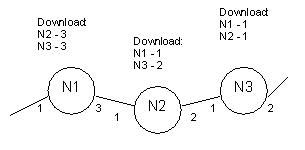
This is obviously very time consuming and inflexible. Every time a new node is added to the network, the databases of all existing nodes have to be updated manually. There is no automatic re-routing possible when one link fails. These restrictions are overcome by introducing the automatic routing protocol IS-IS.
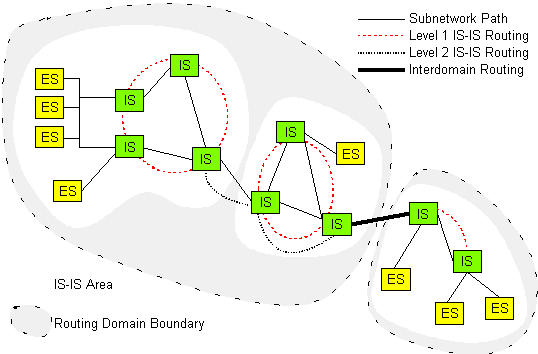
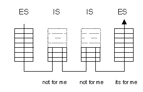
Intermediate Systems use the IS-IS protocol in order to deliver and receive NPDUs from other systems, and relay NPDUs from other source systems to other destination systems. They route directly to systems within their own area, and route towards a Level 2 IS when the destination system is in a different area. When a node receives a data packet, it looks at the destination address. If the packet is meant for the node itself, it passes the data to its transport layer for further processing. Otherwise it checks in its forwarding database, through which interface the data packet has to be forwarded to reach its final destination. This procedure is repeated in every node, which the data packet travels along. The IS-IS protocol provides the automatic generation and update of forwarding databases. This happens in several steps:
First of all every node has to learn about its neighbours. This is achieved by each node sending so called "hello" packets on all its interfaces. They just contain the NSAP address of the node. The sending interval is about 1 second. If a node receives the "hello" packets from its neighbour, it knows which NSAP address its neighbour has and through which interface it can be reached. The link to this node is said to be open. In the same way the link is said to be closed, if the node no longer receives "hello" packets from its neighbour. The node stores the state of all links in its link state database.

The next step is that every node sends the information about its neighbours to the whole network. These packets are so called "Link State PDUs" (LSP). As these packets are forwarded by every node, the information is literally "flooded" through the network. Every node adds the information of a received LSP to its own link state database. Now it knows not only about its own neighbours, but also about the neighbours of other nodes. This allows the node to create a map of the complete network. As all LSPs of all nodes are sent through the complete network, the needed bandwidth increases rapidly with the number of nodes in the network. A node generates LSPs on two conditions:
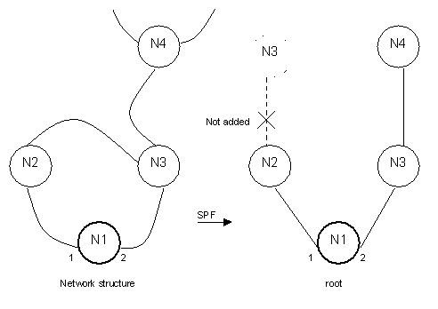
There is also an acknowledgement mechanism for received LSPs. It ensures that all nodes have the same notion of what is the most recent LSP from every other node. The used data packets are called "Sequence Number PDUs". They just list the received LSPs and are used to explicitly acknowledge or request more LSPs. The final step is the calculation of the forwarding databases. Calculation is based on the information of the LSP database ("the network map"). The used algorithm is called "Shortest Path First" (SPF): Every node creates a tree structure with itself as the root. The direct neighbours are added as main branches and then the neighbour's neighbours as subbranches. If one node can be reached via two branches, only the shorter branch is added. Recalculation of forwarding databases happens every time a change in the link state database occurs. The whole algorithm becomes very memory intensive when the number of nodes becomes too big. If the network becomes bigger, it has to be separated into different areas. The above described routing only happens inside one area. It is known as "Level 1" routing.
Level 2 routing also supports routing between different areas. Level 2 Intermediate systems act as Level 1 Intermediate systems in addition to acting as a system in the subdomain consisting of Level 2 ISs. Systems in the Level 2 subdomain route towards a destination area, or another routing domain. With level 2 routing there are one or more dedicated nodes in an area. These nodes ("level 2 routers") not only know about all the nodes in their area but also about the dedicated nodes of other areas. In this way they work as gateways between different areas.
There are several Q3 stack parameters which have to be configured correctly to allow for interworking between different vendor's equipment. Some of them are configured automatically, e.g. by the node itself, whereas other parameters have to be configured by management action.