TMN Information Models - M.3100, G.803
Understanding ITU-T M.3100
Applying OSI Network Management to Telecommunications Networks
Perhaps one of the more popular applications of
OSI network management can be found in the world of
Telecommunications Management Networks (TMN). Much of the lower
layer modeling provided within TMN is based on objects specified
in M.3100. M.3100 in turn bases much of its terminology on the
networking nomenclature defined for the Synchronous Digital
Hierarchy (SDH) by G.803. Data networkers beware! Some of the
terminology used to describe SDH can be a bit confusing at first,
so pay attention to the details. You'll find that concepts such
as connections and acronyms such as TCP have a completely new
meaning. In keeping with the flavor of the relationship of these
standards, we'll first review the general concepts (non-SDH
specific) defined in G.803, and follow up with a discussion of
the objects in M.3100.
G.803 - Defining a framework for modeling synchronous networks
Much of the information presented in the models
of M.3100 are based on concepts defined in G.803. Through this
recommendation, standard forms are provided for the definition of
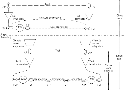
virtual objects within the telecommunications system. Figure 1.
from G.803 depicts many of the components and their relationship
in providing multiple layers of communications service. The
ever-popular Client/Server model is used as a paradigm for
describing the relationship between the layers of synchronous
networks, with the client layer traffic being carried over
transport services provided by the Server Layer.
Two important types of transport entities,
trails and connections, are used to transfer information within
the framework of the client and server layers. A trail, as shown
in Figure 1, is responsible for managing the transfer of
information through one or more client layers via "access
points." A trail consists of trail termination functions
that interact via a network connection. Connections, on the other
hand, are used to transfer information between connection points;
multiple connections can be used to support a single trail within
a layer. As can be seen in the figure, a single layer can contain
multiple connections that serve the information transport needs
of the related client layer.
And just what are these other gizmos in the
figure? you ask. There are several other components in the
general framework defined by G.803. As can be seen in the figure,
the objects include:
- CP - connection point, this is the point
at which the end of a single trail is bound to either
another trail or another connection.
- TCP - Termination Connection Point (not
Transmission Control Protocol). This is a special case of
a connection point where a trail termination and an
adaptation function are bound.
- Adaptation - provides a point of access
between the client and server layers. This function
"defines the "server/client" association
between the connection point and access points.
- Bi-directional reference point - refers to
a point in the network in which a pair of unidirectional
connections or trails are combined to provide full-duplex
connections.
- Network connection - defined by G.803 as a
"transport entity" formed by a series of
"connections between "termination connection
points". In our sample figure, you can see that the
server layer provides a network connection across several
connections to provide a service accessible by the client
layer. This network connection can be used to transfer
client trail information.
- AP - access point. Defined as a
"reference point" where the output of an
"adaptation" source function is bound to an
input of a "trail termination source" or the
output of a "trail termination sink" is bound
to the input of an adaptation sink function." In
simpler terms, each layer's access point is the point at
which a server layer terminates the supporting trail
service.
- MC - matrix connection. Models the
connection within a subnetwork that consists of a
connection that is transferred through a matrix function.
This matrix can either be a fixed matrix (for example, a
permanent circuit through some switching function, or
dynamically, as in the case of an automatically switched
circuit.
If you are developing a TMN supportable model
for managing equipment that you are developing, these concepts
are invaluable. As we will now see, this terminology is a core
element of the M.3100 object model that is one of the standard
components of TMN management architectures.

Figure 1 - Example of functional model fragment (from ITU-T Recommendation G.803)
M.3100 Objects
With the architecture defined in G.803, you can
now apply these concepts as managed objects. By describing the
major system objects in GDMO using the G.803 framework, the
object model can directly map into a familiar framework. Faults
can be correlated to standard system objects ranging from the
point of attachment within a server layer to the trail within the
client layer; ideally, when a service affecting problem occurs,
the source of the fault can be identified for remedial action,
and the effected client services can be reallocated to the
appropriate server trails. Configuration management is
facilitated through providing standard mechanisms for
provisioning and identifying fielded equipment and their
configurations.
M.3100 takes the information developed to
support the SDH models (in G.803), and adds several additional
managed object classes that provide a baseline for developing
application specific models. By using the M.3100 classes,
integration of information models into the larger scale
enterprise vision is possible. As a "Generic Information
Model," M.3100 provides generally useful object classes that
can be applied to support the TMN architecture.
If, for example, you are developing a
mega-switch gizmo with proprietary gizmo circuits, plan on using
M.3100 as a model for breaking down your proprietary gizmo into
the appropriate components. Through the classes defined in M.3100
uniform mechanisms are provided to support fault, configuration,
performance, security and accounting management.
The M.3100 specification is organized into 6
"fragments" that combine to form the Generic
information model. There are both direct containment
relationships between the fragments along with associative peer
relationships. The 6 fragments defined within M.3100 are:
- Network Fragment: defines the relationship
between a managed network and its related trails,
connections, and managed elements. In this case, a
network fragment is shown to contain all elements.
- Managed Element: defines the components
and relationships contained in a single managed element.
In this case, a managed element is shown to contain
equipment (including software), along with trail
termination points.
- Termination Point: The termination point
fragment contains the types of terminations that a single
piece of managed equipment may contain. Both trail and
connection termination points are included in this
fragment.
- Transmission Fragment: Provides a
different, non-equipment oriented view of communications
through a network. In this case, two forms of
transmission entities are defined, trails and
connections. The relationships between these entities and
references to their relative termination points are
included in this fragment. Termination points include
termination point sources, sinks and bi-directional
termination points.
- Cross Connection Fragment: helps in
managing cross connect fabric topologies. In this case,
the cross connection fragment contains multipoint cross
connections, cross connections, generic termination
points, and a pool of termination points.
- Functional Area Fragment: defines the
classes of objects contained within a managed element to
provide additional management services. Object classes
contained in the functional area fragment include:
Management Operations Schedule, Logs (e.g., alarms,
attribute value changes, object creation and deletion
records, state change records), alarm assignment
profiles, event forwarding discriminators and the current
alarm summary control. Of these object classes, with the
exception of the Alarm Severity Assignment Profile, all
are defined either in X.721 or Q.821.
As you can see, through these fragments, M.3100
provides a set of objects to identify network topologies from
several perspectives, and to provide the standard management
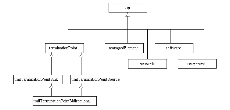
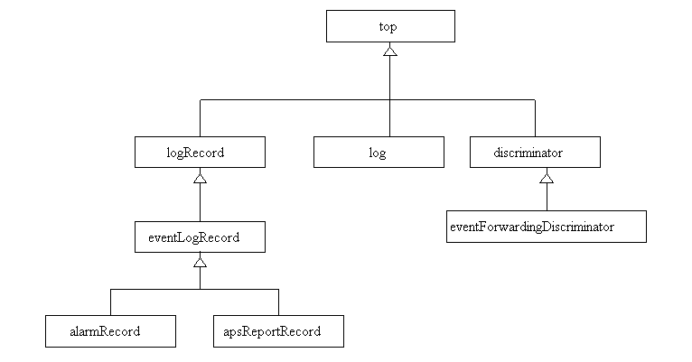
functions. Figure 2 shows the inheritance relationship of many of
the main objects required to support the M.3100 functional
fragments. If you have had an opportunity to read some of the
earlier articles in this series, you may notice that many of
these classes of objects are direct references to X.721. No need
to reinvent the wheel here. The goal is to provide a useful
framework for organizing network management services. The
remainder of the objects in the diagram are defined in the M.3100
specification.

Figure 2 - M.3100 Object Inheritance Hierarchy (Main Fragment)

Figure 3 - M.3100 Object Inheritance Hierarchy (Event Fragment)
The majority of the objects defined within
M.3100 are self-evident in the context of the SDH system
architecture definitions. There are some interesting issues in
developing systems that implement these objects. For example, the
termination point objects can be automatically instantiated by
the managed element, or on the direction of the element
management layer. Similarly, the establishment of associations
between the termination points and their parent connections and
trails is a matter requiring distributed knowledge.

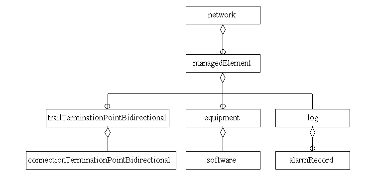
Figure 4 - Containment Hierarchy (Sample Fragment)
As an example of how the objects can be
distributed across the system, take a case in which there is a
system requirement to isolate and recover from a fault within a
finite time period. In the case of a layered solution as
described by these standards, error conditions are likely to be
identified by several objects in managed elements throughout the
system. If the management information network has sufficient
capacity to quickly report the fault conditions to a central
arbiter responsible for network layer management functions, it is
simplest to let the network layer manager handle and recover from
the fault. However, if fault remediation services require a
recovery time shorter than can be reasonably expected from the
management network, it is likely that copies of the layer
management objects may be distributed throughout the network.
Since the standards do not constrain the implementation in these
areas, solutions to these issues can be left to the system
implementers.
As you can see, their is a broad selection of
standards that are targeted toward assisting in the development
of TMN based solutions. Within the last few years, the market for
software components that assist in the realization of TMN
products and management systems has entered a maturation process.
Many major telecommunications carriers have entered into
significant commitments to fielding and implementing TMN based
management architectures. If you are developing equipment that
may be targeted towards this market, and plan on offering your
products to these customers, the development of Q3 capable
interfaces that provide an appropriate set of objects based on
M.3100 is worth serious consideration.


