Win FIR Filter Designer V2.5
Finite Impulse Response Filters
The N tap FIR filter consists of N-1 delayers, N multiplyers, each with
its correspondant values a(j), and N-1 adders, or a global adder. The abbreviation
FIR stands for Finite Impulse Response. Such is the characteristic of the
impulse response of FIR filters. Because of the non-recurse filter structure,
it is finite in duration. Actually it has a duration of N, where N is the
number of taps of the filter.
Figure 1: Structure of a FIR Filter
Figure 2: Convolution formula of a FIR Filter
One noticeable feature of FIR filters in general is their linear phase,
because the delay is equal for all frequencies. This is especially important
in video technology.
FIR Filter Design Principles
The problem of designing finite impulse response (FIR) digital filters
experienced great activity in the early 1970`s. Most of this work was directed
at the problem of optimal filter design, in the weighted Chebyshev sense.
One algorithm for this program, by McClellan, Parks and Rabiner, will design
the optimal Chebyshev approximation for linear phase filters. The Chebyshev
optimization is done very efficiently by means of the Remez exchange algorithm,
and this particular FIR filter design program has found wide use.
The filter design process is always a compromise among filter length,
transition width and passband / stopband deviation (in the bandpass case).
Not all of these specifications can be choosen arbitrarily.
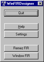
Figure 3: ScreenShot of FIR Filter Designer GUI
Equiripple FIR Filter Design
The method first programmed by Parks and McClellan in FORTRAN, uses an
optimization algorithm called the Remez exchange algorithm. Instead of
describing the coefficients by a Fourier series, they are described using
a polynomial series. This design method allows sharper transitions with
better stopband attenuation than the window method, but there is a ripple
in the passband. This Remez type of design normally produces equiripple
filters, where the ripples in the passbands and stopbands are of equal
height within any one band.
The Remez algorithm also demands very high numerical precision, so
the Win FIR Filter Designer V2.5 uses 64-bit double math precision arithmetic
for all calculations. The program implements two slightly different variations
of the algorithm.
The program provides the possibility to scale the calculated filter
taps to a certain bitwidth. This is of particular interest for all people
who want to implement their filter design on a DSP with integer arithmetic.
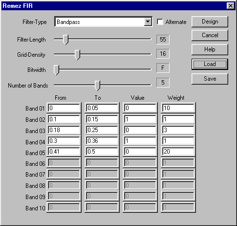
Figure 4: ScreenShot of Remez Design Method GUI
Window Method FIR Filter Design
The window method filter design process is based upon Fourier series. It
is possible to represent a frequency function as a Fourier series, whose
coefficients represent the coefficients of the filter.
To form a casual filter, the Fourier series is truncated and shifted.
Truncating the Fourier series causes a phenomenon called the "Gibbs effect"
- a spike occurs wherever there is a discontinuity in the desired magnitude
of the filter. To counteract this, the filter coefficients are convolved
in the frequency domain with the spectrum of a window function, thus smoothing
the edge transitions at any discontinuity. This convolution in the frequency
domain is equivalent to multiplying the filter coefficients with the window
coefficients in the time domain.
The window design method starts with a very long series, in theory
infinite, that is truncated to the desired length. Coefficients beyond
the truncation are simply ignored. The window removes even more information.
The equiripple method optimizes the series for a given number of coefficients.
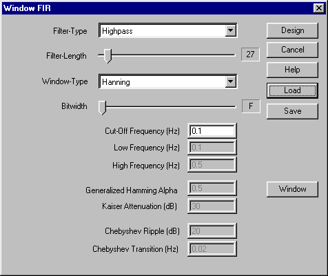
Figure 5: ScreenShot of Window Design Method GUI
Prism
The Win FIR Filter Designer V2.5 features a powerful data plotter module,
called Prism, which displays the impulse response of the designed FIR filter
in the frequency domain either as magnitude, phase, imaginary or real.
The data can be scaled linear or logarithmic, both in the x-axis and in
the y-axis. The filter taps are written to an external file, where they
may be accessed by any third party program.
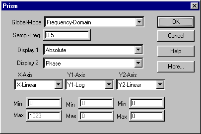
Figure 6: ScreenShot of Data Output Control Window
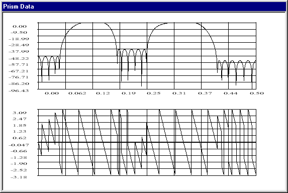
Figure 7: ScreenShot of Data Output Window
Download WinFIRDesigner V2.5 (174 KB)
Sources for FIR Design Algorithms
©
Created by harald.zottmann@cellsoft.de
Last modified 09. April 2004